
|
|
|

|
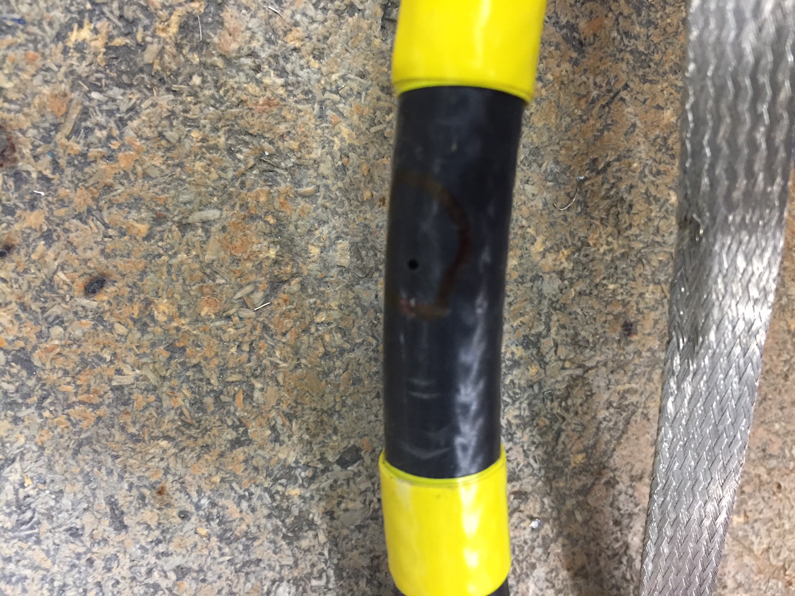
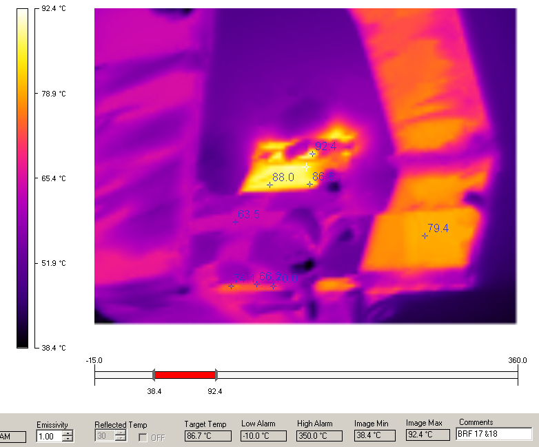
| KPS6N High Voltage Pinhole | BRF17 and 18 Thermal Scan | Booster Toroid Saturation | Booster Mode 2 Oscillation |
This plot is the Proton Torpedo (B124) showing an oscillation in bunch length and relative position. Proton Torpedo data is gathered from a resistive wall-current monitor. FFT analysis produces the bottom left Mode Plot that shows an issue in mode 2.
Looking at the Booster mode 2 damper on B101, the last picture above, shows an error signal for mode 2, suggesting progress can be made by tuning the mode 2 damper.
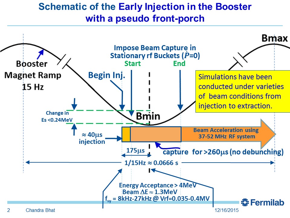
The Booster Early Injection Scheme or EIS, spearheaded by Chandra Bhat, has been fully implemented! Losses haven’t improved as proposed but it is believed that with time and tuning we may be able to reach 98% efficiency (current efficiency is ~92%).
Booster experts are currently battling a phase mismatch between the cavity and the drive. There is a phase detector that produces an error they are tuning on but when they tune the error out the efficiency gets worse. Dig in and tune.

When people talk about 'Recycler Beta Wave' or 'Beta Wave Corrections' they are referring to an error in the machine lattice. When plotted, the error looks like a wave about the design lattice. This plot shows the designed Recycler lattice beta in green and a recent measurement in magenta.
The physical size of the beam at a point in the machine is determined by the beta at that point multiplied by the beam emittance. Recycler beam pipe is shaped like an oval and is significantly smaller vertically than horizontally. The increased vertical beta at 421 and 425 blows the beam up larger than can fit in the vertical aperture causing scraping and high losses. Beta wave corrections have been tried that do lower the losses at 421 and 425, but have resulted in the beta function increasing elsewhere in the machine where the beam scrapes instead. Work is ongoing to optimize these corrections to lower Recycler losses ring wide.
Operators should always be looking not to increase losses while tuning but sometimes our procedures encourage us in another direction. Many of you may have experienced this lately with the Recycler dampers occasionally needing re-phasing after an RR LLRF trip.
The dampers plots don't look like the traces from our old instructions and this is because we are running 4+6 slipstacking now and when the procedure was developed we were running 6 batch boxcar. The fuzz that starts shortly after the fourth batch is injected is due to slipstacking. We can still use the first three batches that are clearer to get us into the right ballpark. Once in the right ballpark, check on the losses to make sure we're optimized.
If you are interested in contributing or have a suggestion for a topic, please email beau@fnal.gov